| Specifications: |
| MAX. Power in |
100 WATT |
| V.S.W.R |
1.00:1~19.99:1 |
| Frequency Range |
125MHz~525MHz |
| Insertion Loss |
< 0.15dB(VHF) , < 0.25dB(UHF) |
| Temperature |
0℃~70℃ |
| Battery Build -in |
3.7V Li-ion Battery |
| Size(without SMA |
25*25*60 (mm) |
| Power in |
5V (micro usb) |
| Interface (in and out ) |
SMA female |
| Impedance: |
50Ω |
| Weight |
160g |
Features function
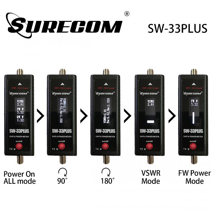
Push red button and hold 2 sec. to" Power on " and "ALL "mode " LCD display show 
Push red button -" 90° "mode , LCD display show 
Push red button -" 180° "mode, LCD display show 
Push red button -" V.S.W.R. "mode ,LCD display show 
Push red button -" FW POWER "mode ,LCD display show 
Push red button and HOLD -" POWER OFF
1.1How to use Power meter (forward)
Push red button -switch on
Push red button at four times to mode "POWER meter " ,LCD display show 
Connect the SMA (mark TX) to Radio output .
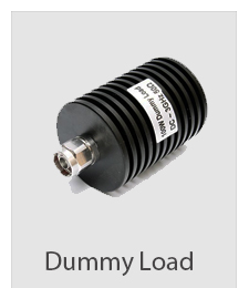
Connect the SMA to DUMMUY Load
Caution : Please use correct dummy load , High power will damage the dummy load.
1.2 How to measure SWR?
All forms of SWR meters measure SWR, standing wave ratio on a transmitter feeder. Using SWR meter is relatively easy, but one should be able to interpret the results when using it. In general, VSWR and SWR are the same.
When using VSWR meters to measure the the performance of a new antenna, always one should prefer to use up to 3W power and a clear channel. The following procedure can be used to use the meter.
Push red button at two times to mode "V.S.W.R. meter " ,LCD display show 
Connect the SMA (mark TX) to Radio output .
Connect the SMA (mark Ant) to ANTENNA
When the the LCD show 1.00 to 1.50 , 1.0~ 1.5:1 mean the antenna is suit the frequency.
When the the LCD show 1.50 to 3.00 , 1.5~ 3.0:1 mean the antenna is not good suit the frequency.
When the the LCD show 5.00 to 19.99 ,5.0~19.99:1 mean the antenna is not suit the frequency.
The VSWR meter is connected in the feeder from the transmitter to antenna. For the feeder convenience, SWR meter is located at the transmitter end of the feeder. This helps to monitor the actual VSWR values.
One should know, where exactly SWR can be measured. There is always some degree of feeder loss, which has a major effect on the VSWR readings.
Feeder loss absorbs power in both directions. When the reflected signal is reduced, there is a high level of feeder loss. The reflected signal gets reduced as a forward signal to the antenna, later it’s reflected back to the transmitter.
Since the signal is reduced on its way to the transmitter, an antenna with poor match and high VSWR will be fine at the transmitter. Hence, when a feeder that induces a high loss is used, VSWR is good at the transmitter, but at the antenna, it may be poor.
SWR Formulas and Calculations
VSWR can be calculated from various parameters. By definition, VSWR is given as ratio of maximum voltage on the line to the minimum voltage.

The same can be expressed in terms of forward and reflected wave voltages.

Package Contents
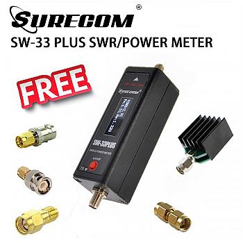
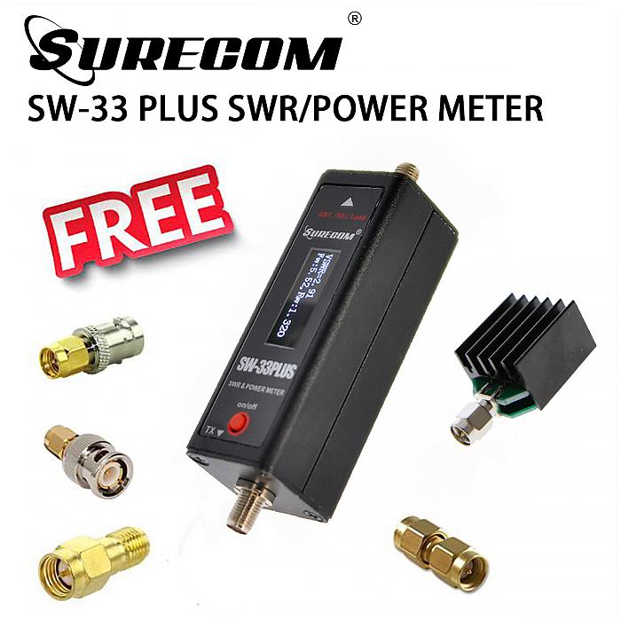
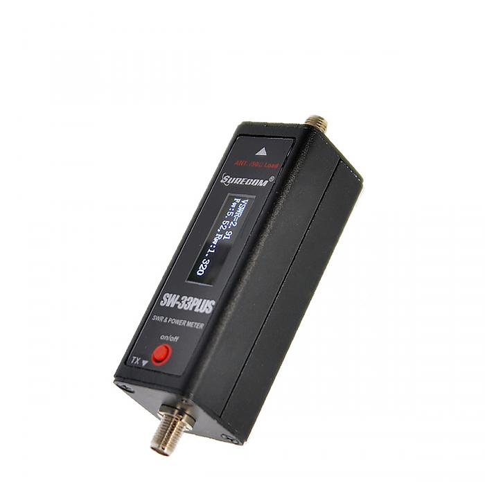
1x SW-33 PLUS SWR/POWER METER
1x English User Manual
1x USB charger cable (Not include Power adaptor)
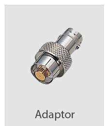
1x SMA male to SMA male Adaptor
1x SMA male to SMA female Adaptor
1x SMA female to BNC female Adaptor
1x SMA male to BNC male Adaptor
1x 5-20W DUMMY LOAD for testing / other type of 5W dummy load for testing (random)


